
The field of fibre optics communications has exploded over the past two decades. Fibre is an integral part of modern day communication infrastucture and can be found along roads, in buildings, hospitals and machinary.
The fibre itself is a strand of silica based glass, it's dimensions similar to those of a human hair, surrounded by a transparent cladding. Light can be transmitted along the fibre over great distances at very high data rates providing an ideal medium for the transport of information. This section will provide explainations for some of the terms associated with the field of fibre optic engineering for telecommunications.
This list is not exhaustive nor are the subjects treated in depth, have a look at our recommended text section to learn more...
 Fibre Structure
The diagram shows the typical structure of a fibre used for communication links. It has an inner glass core with an outer cladding. This is covered with a protective buffer and outer jacket. This design of fibre is light and has a very low loss , making it ideal for the transmission of information over long distances.
Light in a fibre
The light propagates along the fibre by the process of total internal reflection. The light is contained within the glass core and cladding by careful design of their refractive indices. The loss along the fibre is low and the signal is not subject to electromagnetic interference which plagues other methods of signal transmission, such as radio or copper wire links.
The signal is, however, degraded by other means particular to the fibre such as dispersion (described below) and non linear effects (caused by a high power density in the fibre core)
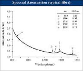

Image courtesy of Corning Optical Fiber
Attenuation
The loss, or attenuation in fibre depends on the wavelength of the light propagating within it. The image shows the attenuation spectrum of a typical single mode fibre used within the telecommunications industry. There are three main bandwidth 'windows' of interest in the attenuation spectrum of fibre. The 1st window is at 800-900nm, here there is a good source of cheap silicon based sources & detectors. The 2nd window is at 1260-1360nm, here there is low fibre attenuation coupled with zero material dispersion (see dispersion ) . The 3rd window of interest is at 1430-1580nm where fibre has it's attenuation minimum. Typically the telecommunications industry use wavelengths in the 3rd window which coincides with the gain bandwidth of Fibre Amplifiers (see EDFAs ) In the future the search for greater bandwidth is likely to open up other windows for fibre transmission.
 |
Return to Jodrell Bank Home Page |  |
Return to Fibre Optics Group Home Page | 
| Return to top |
Web page written by: Roshene McCool rmccool@jb.man.ac.uk