The MKIA Radio Telescope
The MKIA Radio Telescope
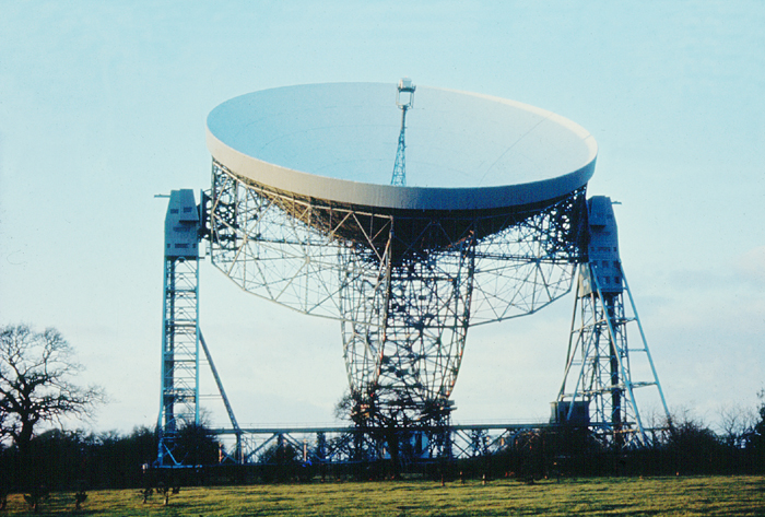
By the late 1960's it was becoming apparent that the steelwork supporting the bowl in the vicinity of the tower tops was being over stressed. A plan was thus drawn up to take away around a third of the load from the towers and pass it through two large semi-circular wheel girders to a new central rail track.
However it was vital that the rotation axis (the line through the elevation bearings) still remained very close to the centre of gravity of the combined bowl and wheel girder structure otherwise it would not be possible to rotate the bowl in elevation. To counter balance the new wheel girders it was thus necessary to place additional weight on the far side of the axis. This was done in by far the most productive way - by building a new surface within the old!
The original surface was a a deep parabaloid with its focus in the plane of the aperture. This gave it excellent protection from interference, but also meant that the effective collecting area was less than optimum. The new surface was shallower, with the focus well out from the aperture, as you can see from the photograph of the focus box. There is a gap between the old and new surfaces at the edge corresponding to the vertical rim, but this increases considerably at the centre. The result is an improvement in sensitivity as a result of the greater effective collecting area.
The surface was made and set to a better accuracy than that of the MKI so the upgraded telescope could provide a useful effective collecting area at frequencies as high as 5 GHz - so increasing the scope of observations that it could carry out.
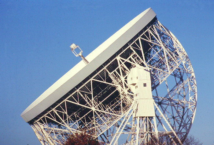
The Central Tower and Focus Box
The opportunity was taken to replace the analogue computer control system with the Ferranti Argus 100 computer that had originally been used to control the MKII telescope.
The focus box contains the receivers which first amplify the incredibly weak signals collected by the telescope. Developments over the years have gradually improved them so that now they generate far less noise themselves so allowing us to detect much weaker signals. The present receivers use special HEMT transistors which are cooled to around 15K using Helium refrigeration systems.
Following a winter storm on the 2nd Jan 1976, when peak wind speeds of over 90 mph were recorded at Jodrell Bank severly testing the telescope structure, two diagonal bracing struts were added from the base of the two towers to just above the azimuth bearing. These give it greater rigidity in the direction along the towers which is alligned to the wind when the telescope is parked in the zenith to ride out storms.
On the telescope's 30th anniversary in 1987, it was renamed the Lovell Radio Telescope in honour of Sir Bernard Lovell.

