
Introduction
The concept of an abstraction of implementation specific details from the creation of an astronomy specific computing grid was introduced in the IVOA Note "A Proposal for a Common Execution Architecture" [CEA] which described the motivation for and benefits of such an abstraction as well as the concrete schema and web interface definitions that were used by the Astrogrid [AG] implementation of the system at the time. The description of CEA is now split into two parts
- The data model for an application, as defined in this document. This model is a general description of what parameters a particular application can accept, and as such it may be regarded as a "language" that is implementation independent to describe at the user-level how the application should be called.
- A specific web interface (defined in the [CEAIMP] document) for remote invocation of applications that conform to the CEA. The web interface can take a
toolXML instance document describing the desired application invocation and actually run the application and return the results in an asynchronous, secure fashion that is consistent with the Universal Worker Pattern ([UWS])
This split between the application model and interface emphasises the fact that the application model could be re-used in other circumstances.
The schema that are presented in this document represent an evolution of those presented in [CEA] that incorporates both
- Updates to the style and content of the schema to make them consistent with the version 1.0 registry schema model as described in VOResource: an XML Encoding Schema for Resource Metadata [Plante et al. 2006] (hereafter refered to as the VR)
- Updates to the design of CEA itself as a result of requests for enhanced functionality as a result of the experience gained in writing and operating CEA based services.
The CEA Application Data Model
As presented in [CEA] the basic model for an application is simply a process that can expose a number of "interfaces" which each may have a number of input and output parameters. This means that the UML domain model for the application description is relatively simple as displayed below;
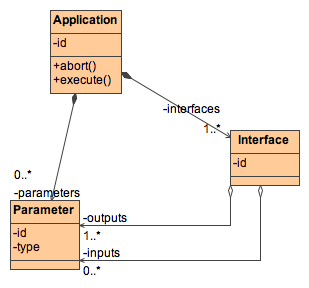
It is important to realise that the parameter definitions can be reused in multiple interfaces (indicated by the fact that the interfaces are aggregations of parameters) and that the final xml schema representation reflects this by defining all of the parameters for an application first, and then defining the interfaces which contain references to the original parameter definitions.
Design Aims
The main design aims are;
- produce a description of an application to allow it to be successfully invoked with the correct parameters, with a degree of validation of the parameters possible before sending to the application.
- be able to use the description to build a dynamic user interface for specifying the parameters for an application.
In addition the model also needs to be able to specify
- parameter types
- logical groupings of parameters
- indicate parameters that have to be given together for semantic reasons
- indicate parameters that should appear "together" in a user interface.
More detail
This diagram does not show the full model that is expressed in the schema, however, a more detailed UML diagram to represent the all of types used in the Application Data model is in Appendix D. The additional complexity that is present in this diagram results from
- The ability to specify detail about each parameter definition e.g. default values, ranges etc..
- The ability to group and conditionally repeat parameters in an interface.
Detailed Description of the CEABase Schema
The two major types within the schema are
- ApplicationDefinition - This is the description of an application
Tool- This represents an invocation of an application.
ApplicationDefinition
The main type that is used to describe an application is the cea:CeaApplication which is derived from va:Application, which in turn is derived from vr:Resource. This means that the start of a such a description would be as below, where the elements possible in the region marked "..." are described in [VR] and [VA] - the CEA specific part starts with the <applicationDefinition> element.
   <Resource xsi:type="cea:CeaApplication"
      created="2005-09-09T12:28:16" updated="2005-09-09T12:28:16" status="active">
      <title>SExtractor</title>
      <shortName>SExtractor</shortName>
      <identifier>ivo://org.astrogrid/SExtractor</identifier>
...

      <applicationDefinition>
ApplicationType
Parameters
The first elemtent of the <applicationDefinition> is the <parameters> element. Parameters are defined once per
application, and each parameter is defined with a <parameterDefinition> element which is of type ceab:BaseParameterDefinition, which in turn is derived from vs:BaseParam. This means that the possible attributes and sub-elements of the <parameterDefinition> are listed below.
id attribute
This is the identifier for the parameter - the references to parameters in the interfaces use this value as the parameter identifier.
type attribute
The type of a parameter is CEA is a rather broad concept, with the type ranging from standard atomic types, to aggregate 'types'. The choices were made based on an empirical survey of the most common kinds of parameter that occured in the original target application for CEA namely typical astronomical legacy command-line application. In this sense the types are not intended to be "complete", but to represent a useful subset of all possible types.
It should be noted that the formal type of the parameter value that is passed in the Common Exectution Connector [CEAINT] interface is always an xsd:string - any interpretation of this type information is done at the client or the server, but not by the transport protocol.
The choice of what type to declare a parameter is largely a matter of the how much processing or validation of the parameter that the application designer wants the CEA infrastructure to perform - it would be possible to delare just about any parameter as text of binary for instance, which would imply no validation or processing of the value by the CEA client or server.
The server side representation of the parameter is determined from the form of the defaultValue element. A concrete example of this is that a boolean value may be represented in many ways on the client as in the table below, but it might be that on the server side that only true/false can be understood, so the defaultValue would be declared 'true'. The server side treatment of parameters is largely implementation dependent, however, the treatment described in this paragraph is that performed by the 'Commandline Common Excecution Controller' [CEAIMP] and as such possibly should be addressed by a separate implementation defined attribute.
| type | Description | String representation |
|---|---|---|
| integer | an integer value | |
real |
a real value (any precision) | |
| complex | a complex number pair | |
| text | any data that could be interpreted as human readable text in a well known encoding. | |
| boolean | a boolean value | 0/1 true/false yes/no on /off |
| anyURI | a string that could be interpreted as a URI. | |
| VOTable | a VOTable conforming to the IVOA specification | |
| RA | Right ascension | sexagesimal allowed |
| Dec | ||
| MJD | Modified julian data | |
| DateTime | A date and time in ISO 8601 format | |
| ADQL | Astronomical | |
| binary | arbitrary | |
| FITS | a file conforming to the [FITS] standard | |
| xml | arbitrary xml | the schema for the xml is optionally indicated in the UType of the parameter |
Future versions of the allowed enumerations for values of this attribute will be influenced by the work of other IVOA standards working groups, particularly in the areas of Semantics, Theory and Applications.
array attribute
If present this attribute specifies that the parameter is an array, and it also defines the shape and size of the array. This definition is essentially the same as for the arraySize attribute in VOTable [VOTABLE], where the first specified dimension changes fastest, and the final dimension can be specified as an asterisk which means unbounded, or an integer followed by an asterisk which means guarenteed to be less than or equal to the attribute.
array="64*10*x"
Note that strings (the text type above) do not follow the same conventions as VOTable in that they are not considered as arrays of characters.
name element
This is used to present a name of the parameter in a user interface - This is included because the id attribute of the parameter will often be tied to the name that the underlying application uses, and that name might not be very "human-readable".
description element
This can be used to present a human-readable description of the purpose and meaning of the parameter.
unit element
The physical unit of the parameter. The actual strings used to denote units follow the same conventions as for the unit attribute of [VOTABLE].
ucd element
A UCD for the parameter if appropriate.
UType element
The UType of the parameter if appropriate.
mimeType element
The mimeType of the parameter if appropriate.
defaultValue element
A default value for the parameter - note that this is simply for presentation to the user interface - in a tool element the value for the parameter should be explicitly given - it is not part of CEA that the parameter description will be reparsed to obtain a default value for a missing parameter.
optionList element
This can be used to specify that a parameter can have only an enumerated list of values. The client is expected to enforce this requirement.
<optionList>
<optionVal>NONE</optionVal>
<optionVal>BLANK</optionVal>
<optionVal>CORRECT</optionVal>
</optionList>
range element
This element can be used to specify the range of values that a parameter may have
Interfaces
An application needs at least one interface to be callable. Interfaces are identified by their "id" attribute. The 4 possible sub-elements of the <interface> element are
- <constants> - parameters that should have a constant value for the interface are defined here by using <pval> elements, which are described below. These constants are intended to be supplied by the server side of a CEA application.
- <input> - the input parameters for the application.
- <output> - the output parameters for the application.
- <description> - an optional description of the interface that could be used to present a description in a user interface.
The exact order and grouping of parameters within the input and output sections is made using the pref, pgroup and cgroupHead elements which are described in more detail below
pref
This element is the principal method of making a reference to a parameter definition, and the use is illustrated below.
      ...
            <parameterDefinition id="PHOT_APERTURES"
               type="integer">
               <name>Photometry apertures</name>
               <description>
                  MAG_APER aperture diameter(s) in pixels
               </description>
               <ucd />
               <defaultValue>5</defaultValue>
            </parameterDefinition>
         </parameters>
         <interfaces>
            <interfaceDefinition id="qa">
               <input>
                  <pref maxOccurs="1" minOccurs="1"
                     ref="PHOT_APERTURES" />
      ...
The ref attribute of the pref element must have a value that corresponds to the id attribute of a <parameterDefinition> to make a valid reference to a parameter in an interface, as illustrated by the blue text in the example above. In addition the <pref> element can have the following attribute
- minOccurs
- The minimum number of times that the parameter should occur in the interface. The default value is 1.
- maxOccurs
- The maximum number of times that the parameter should occur in the interace. A value of 0 is interpreted as the parameter being allowed to be repeated an unbounded number of times. The default value is 1.
- hidden
- If true this is a hint to a client side GUI builder that this parameter should be hidden
pgroup
A <pgroup> element can be used to group parameters in the interface. This grouping can be done for two primary reasons.
- To specify that a set of parameters should be repeated as a group
- To give hints to the client side GUI builder that the parameters should be presented to the used in a grouped fashion.
The example below shows that the 'targets' and 'matches' parameters should be repeated as a pairs (if at all, as minOccurs takes the default value of 1).
               <input>
                  <pgroup maxOccurs="2">
                     <pref ref="targets" />
                     <pref ref="matches" />
                  </pgroup>
                  <pgroup>
                     <pref ref="matchRadius" />
                     <pref ref="radMax" />
                  </pgroup>
cgroupHead & cgroup
These constructs allow a set of alternative groups of parameters to be required dependent on the value of another parameter. In the example below different parameters need to be specified depending on the value of the 'output' parameter - if it takes on the value of "html" then a parameter called "htmlversion" will be required, and if it has the value "VOTABLE" a parameter 'votableserialization' will be required.
                  <cgroupHead ref="output" >
                     <cgroup name="html options">
                        <value>html</value>
                        <pref ref="htmlversion" />
                     </cgroup>
                     <cgroup name="votable options">
                        <value>VOTABLE</value>
                        <pref ref="votableserialization" />
                     </cgroup>
                  </cgroupHead>
As well as giving instruction to a client side GUI building tool, the cgroupHead and cgroup constructs should also be used by the server side CEA component to do basic validity checking on the parameters that it actually receives.
Tool
The ceab:Tool type represents an invocation of the application, i.e. it specifies which interface to use and supplies values for all of the necessary parameters. This is principally of interest of course when calling an application via the CEA interfaces and is discussed more fully in [CEAINT]. An important feature of CEA is that the parameter values that are passed to the server side CEA component are fully specified by this <tool> element, and the description of the application specified by ApplicationDefinition is used by the server side CEA component merely for validation purposes - no parameter value would be changed by the server side CEA component. The application that is to be run is identified by the id attribute and the particular interface by the interface attribute of the tool element.
pval
The <pval> element is the principal element that carries parameter values, which are always passed within a <value> element, whether directly or within an <array>. The schema type of the value element is always xs:string.
<tool xsi:type="ceab:Tool" xmlns:ceab="http://www.ivoa.net/xml/CEA/base/v1.0"
   xmlns:xsi="http://www.w3.org/2001/XMLSchema-instance"
   xsi:schemaLocation="http://www.ivoa.net/xml/CEA/base/v1.0 ../v11/CEABase.xsd"
   id="ivo://dummy" interface="test">
   <input>
      <pval id="p1">
         <array>
            <value>1</value>
            <value>2</value>
         </array>
      </pval>
      <pval id="p2">
         <value>hello</value>
      </pval>
   </input>
   <output>
      <pval id="out" indirect="true">
         <value>vos://org.test!vospace/mydata</value>
      </pval>
   </output>
</tool>
Note on ordering of parameter values.
Generating User Interfaces
Names and descriptions
Default Values
Default values where specified for parameter values are intended for client side GUI builders only, and are not substituted by the server side components for missing parameters.
Validity Checking
The client should attempt to perform validity checking on parameters wherever possible, however this is not manadatory as the server must perform validity checking of parameters and will reject requests to run applications with invalid parameter value specifications.
Repeatable parameters
Where a parameter is repeatable (or deletable) the GUI should attempt to inform the user of such a possibility to the user either by using some direct visual form such as an icon next to the parameter input widget, or by enabling or disabling a "repeat parameter" functionality in another GUI element such as a toolbar or pop-up menu when the parameter is selected.
Parameter Groups
One of the intentions of parameter groups is to provide formatting hints to a client producing an automatic user interface. The client should attempt to show this grouping by means of devices such as "tab panes".
needs diagram illustrating typical GUI widgets
Registering CEA Applications and CEA Services
To register CEA Applications and services, types from the VOCEA.xsd schema need to be used. The relationships between the types defined by that schema are illustrated below. The main type that is used to register the description of an application is a CeaApplication, which contains standard Resource metadata, as well as an <applicationDefinition > element which contains the actual CEA application description as detailed in the desciption of the CEABase schema above. A service that can run one or more of CEA Applications is registered with a Service type that has a <capability> element of type CeaCapability. The CeaCapability lists references to the ivoa identifiers of the CeaApplications that particular service can offer, as well as detailing which particular CEA interface can be used.
The preceding paragraph describes all of the structures necessary to register CEA applications and services, however there is one convenience type CeaApplicationExtension that can be useful in describing a family of similar applications. The CeaApplicationExtension defines a limited form of application description subclassing, in that it is assumed to inherit all of the parameter and interface definitions of the parent CeaApplication (the one referred to by the extends attribute). It is then allowed to define additional parameters and interfaces, but it should be considered an error if the CeaApplicationExtension tries to redefine an existing parameter.
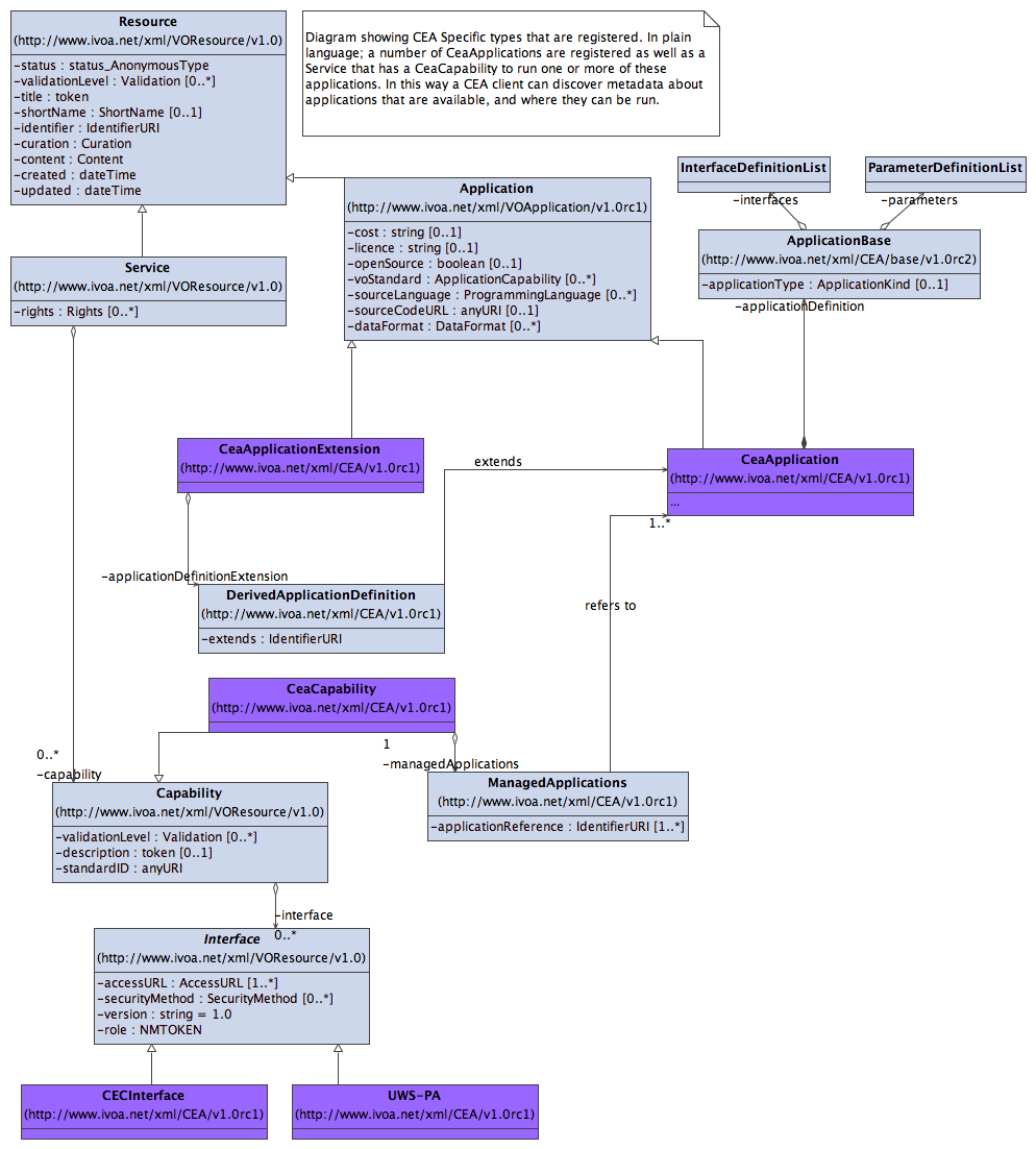
There is a fully annotated example of the registration entries for a CEA application and server in appendix C
Recommendations for Application Description Authors
Validation
Optional Parameters or different interfaces? TBC
Comparision with other "Parameter Models" TBC
There have been a number of other parameter systems implemented in astronomical software systems and it is worthwhile to see the ways in which CEA is different and also the features that CEA has copied to obtain a deeper understanding of the best ways to use the CEA Model.
AIPS
IRAF ICL
Starlink ADAM
- CEA does not attempt to define any sort of parameter storage mechanism for presenting the "current" values of parameters in the user interface.
- The formal (XML) type of the parameter values that is passed is always of type string
Summary of updates since [CEA]
The following represent updates to the CEA Application model since the publication of the original IVOA Note [CEA].
- Schema have been changed to conform with VOResource 1.0 style
- new "Capability/Interface" model
- element capitalization changed
- local elements are in "null" namespace.
- The number of schema files and hence namespaces has been reduced.
- A number of types have been factored out as "implementation details", and moved to another schema that does not form part of this specification.
- Changes to the application model
- parameters may be arrays as well as scalar.
- UType description of parameter.
- parameter groups
- grouped repetition.
- GUI grouping.
- possibility of a group being required dependent on value of another parameter.
- repeatable output parameters.
- cea:CeaApplicationExtension.
Appendix A: The complete CEABase Schema
Note that this schema can be found on-line at http://www.ivoa.net/xml/CEABase/v1.0 (i.e. the target namespace can also be used as a URL for the schema.) This location should represent the definitive source, the schema is only copied below for completeness of this document.
Appendix B: The complete VOCEA Schema
Note that this schema can be found on-line at http://www.ivoa.net/xml/VOCEA/v1.0 (i.e. the target namespace can also be used as a URL for the schema.) This location should represent the definitive source, the schema is only copied below for completeness of this document.
Appendix C: An example VOCEA Instance
Appendix D: Full UML diagram for VOCEA and CEABase schema
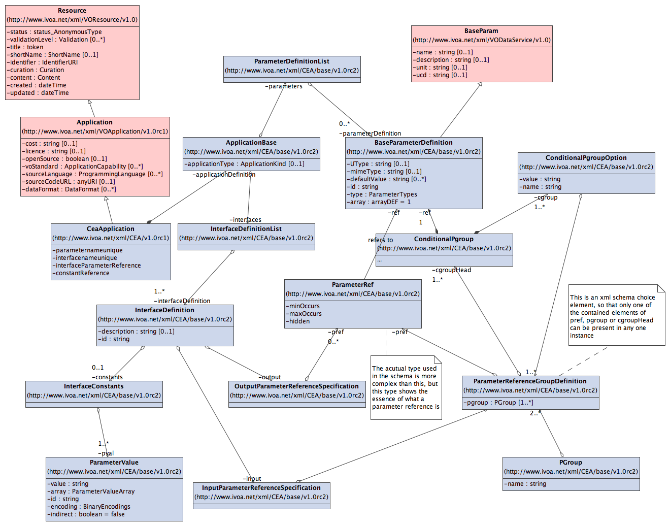 This diagram presents more detail than the average author of a CEA application definition will need to understand as instance documents typically have a simpler looking structure because of the choice of common element names. It is included as a aid to authors of CEA based service implementations where the detailed relationships could be more important.
- The diagram represents the relationships with other IVOA standard schema types, which are displayed in pink.
- The full lists of possible attribute values are presented.
- It is representing the types in the XML schema rather than a conceptual model, and the style of schema authoring dictated by [VR] mandates a number of intermediate types that would not be necessary in other styles.
Appendix : Change History
This is the first version that has been made public - it is derived from IVOA WG wiki content, and the original [CEA] document.
References
- [RFC 2119]
- Bradner, S. 1997.
Key words for use in RFCs to Indicate Requirement
Levels, IETF RFC 2119,
http://www.ietf.org/rfc/rfc2119.txt - [RM]
- Hanisch, Robert (ed.) 2004. Resource Metadata for the Virtual Observatory, Version 1.01, IVOA Recommendation,
http://www.ivoa.net/Documents/REC/ResMetadata/RM-20040426.htm - [VR]
- Plante, Ray (ed.) 2006. VOResource: an XML Encoding Schema for Resource Metadata, IVOA Working Draft,
http://www.ivoa.net/Documents/latest/VOResource.html - [VA]
- Harrison, Paul. (ed.) 2007. VOApplication: an XML Encoding Schema for Application Resource Metadata, IVOA Working Draft,
http://www.ivoa.net/Documents/latest/VOApplicationDM.html - [VSTD]
- Harrison, Paul. (ed.) 2007. VOStandard: an XML Encoding Schema for IVOA Standards, IVOA Working Draft,
http://www.ivoa.net/Documents/latest/VOResource.html - [VOTABLE]
- Ochsenbein & Williams. (eds.) 2004. VOTable Format Definition, version 1.1,
http://www.ivoa.net/Documents/latest/VOT.html - [UCD]
- Derriere et. al. 2004. An IVOA Standard for Unified Content Descriptors, version 1.10,
http://www.ivoa.net/Documents/latest/UCD.html - [CEA]
- Harrison, Paul. 2005. A Proposal for a Common Execution Architecture , IVOA Working Draft,
http://www.ivoa.net/Documents/latest/CEA.html - [CEAINT]
- Harrison, Paul. 2007. CEA Interfaces: How to Invoke Applications in the Common Execution Architecture, IVOA Working Draft,
http://www.ivoa.net/Documents/latest/CEAInterface.html - [xml]
- Bray, Tim, Paoli, Jean, Sperberg-McQueen, C. M., Maler, Eve, Yergeau, Francois (editors) 2004, Extensible Markup Language (XML) 1.0 (Third Edition), W3C /TR/REC-xml
- [schema]
- Fallside, David C., Walmsley, Priscilla (editors) 2004,
XML Schema
Part 0: Primer Second Edition, W3C Recommendation 28
October 2004,
http://www.w3.org/TR/xmlschema-0/ - [ISO8601]
- Wolf, Misha and Wicksteed, Charles 1997,
Date and
Time Format,
http://www.w3.org/TR/NOTE-datetime. - [OAI]
- Lagoze, Carl, Van de Sompel, Herbert, Nelson, Michael, and
Warner, Simeon 2004,
The Open Archives Initiative Protocol for Metadata Harvesting,
http://www.openarchives.org/OAI/openarchivesprotocol.html. - [ID]
- Plante, R., Linde, T., Williams, R., Noddle, K. 2005, IVOA Identifiers v1.1,
http://www.ivoa.net/Documents/REC/Identifiers/Identifiers-200505XX.html. - [FITS]
- FITS: Flexible Image Transport Specification, specifically the Binary Tables Extension, http://fits.gsfc.nasa.gov/.
- [WSDL]
- Christensen, E., Curbera, F., Meredith, G., Weerawarana, S.
Web Services Description
Language (WSDL) 1.1, W3C Note 15 March 2001,
http://www.w3.org/TR/wsdl. - [SOAP]
- Box, D., Ehnebuske, D., Kakivaya, G., Layman, A., Mendolsohn,
N., Neilsen, H.F., Thatte, S., Winer, D.
Simple Object Access Protocol (SOAP) 1.1, W3C Note
08 May 2000,
http://www.w3.org/TR/2000/NOTE-SOAP-20000508/.
Last modified: 04-May-2007 3:33