Supplementary Material
to:
An Introduction to Radio Astronomy
4th edition Cambridge University Press 2019
Last updated 3/07/2019
Chapter 10: Aperture Synthesis
The JVLA Observers Reference Manual: a mine of information
The JVLA Observers reference manual https://science.nrao.edu/facilities/vla/docs/manuals/oss/performance/referencemanual-all-pages contains wide range of useful information in succinct form over and above the specifics of VLA observations. It illustrates and complement the much of the text in chapter 10
Interferometric Imaging
– developing methods
WSRT image showing coherent
”ring lobes”
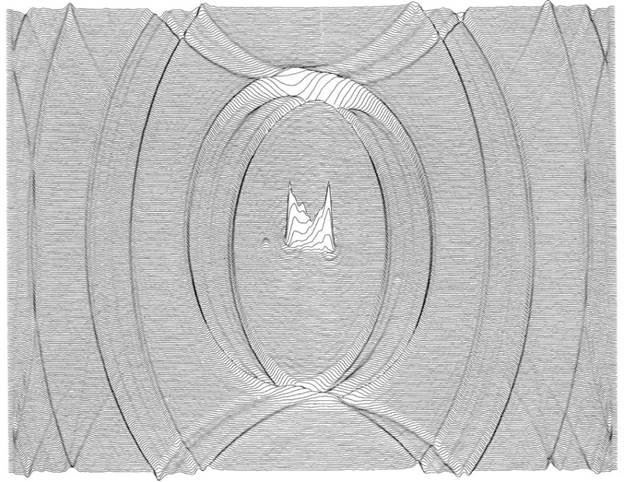
Early aperture synthesis imaging (Section 10.9) : First and second generation E-W arrays
were arranged to sample the u,v plane with uniform spacings in order
to concentrate the sidelobes at well- defined positions across an synthesised
image; these were termed ”grating” or ”ring” side- lobes for obvious reasons.
This arrangement makes the dirty image relatively easy to interpret, without
deconvolution, if the grating lobes fall outside the emission region of interest.
These concepts are well described by Hogbom & Brouw (1974) from which paper this image, made from a
single 12h scan with the Westerbork Synthesis Radio
Telescope (WSRT), was taken. It shows a
ruled-line map of the double radio source 3C452 with the grating lobes
well-separated from the source.
Reference: Hogbom, J. A. & Brouw, W. N.
Astronomy and Astrophysics, Vol. 33, p. 289 (1974)
Imaging the Black Hole Shadow in M87:
The VLBI imaging methods originally developed in the 1970s (see section 10.10) found their latest important application in the imaging of the black hole shadow in M87 by the Event Horizon Telescope (Event Horizon Consortium: Paper IV (2019) see also the entries in Supp. Mat. Chapters 9 and 11). One of the routes to forming the final published image used the now-classical self-calibration plus CLEAN methodology which in turn developed from the “hybrid mapping” technique using the visibility closure phases.
Reference:
Event Horizon Consortium: Paper IV (2019) https://arxiv.org/abs/1906.11241
The
power of modern synthesis imaging:
Snapshots
plus MFS producing an image of M82
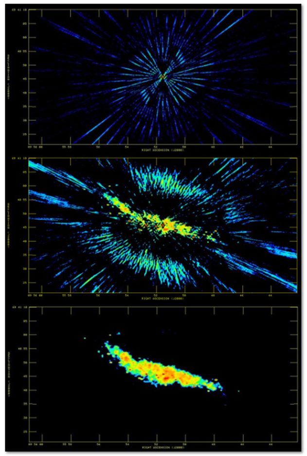
The simulated
images in the text (Figs 10.10 and 10.14) illustrate the steps in the
reconstruction of a simple point double source from the u,v data
delivered by a 6-element non-uniform array (eMERLIN)
and an extended time track. In this case
the dirty beam is easily recognizable in the dirty map. In the three images here we illustrate power
of current synthesis image reconstruction when the dirty beam is complicated
and so is the target source. The
relatively limited u,v data of the starburst galaxy M82 were obtained
from 8 x 2m scans taken over a period of 2h with the JVLA. Within each scan the
data were taken in contiguous frequency channels over the range 5.5-7.5 GHz and
hence formed a multi-frequency synthesis (MFS) data set. The dirty beam (top) and
dirty map (centre) show an admixture of sidelobes due to the limited u,v
coverage plus MFS effects. The CLEAN map (bottom) reveals the central region of
M82 with the point sources being supernova remnants (see also the images in
Sections 13.11 and 16.1 and in Supplementary Material Chapter 16). These images show the power of MFS
coupled with non-linear deconvolution to recover a useful image despite the
short amount of time spent on source. In the course of their research radio
astronomers seek to
optimise the trade-off between on-source time and the size of the
sample which can be observed within a given “wall clock” time (credit: Tom Muxlow).
Production of a multi-configuration VLA image of Hercules A
The power of modern
synthesis imaging is also demonstrated by the superbly detailed image of
the radio galaxy Hercules A shown in Supplementary Material Chapter 16.
It was constructed from a combination of long-track data sets from the
27-element VLA in its D, C, B and A configurations. The smaller configurations
are sensitive to the smooth extended emission whilst the larger ones emphasise
the higher brightness structure within the anti-parallel jets. This process is illustrated at https://www.nrao.edu/pr/2012/herca/ and also in a short video https://www.youtube.com/watch?v=B93-zx3wzmc. To achieve the highest image
quality required the commitment of large amount of telescope time.
Basic interferometric imaging: resources.
The tutorial material offered in Unit 4 of the UK’s Development in Africa
through Radio Astronomy (DARA) programme
can be found at https://jradcliffe5.github.io/Development-in-Africa-Unit-4/
“Friendly VRI” – A virtual Radio Interferometer application. It is designed to simulate astronomical observations using linked arrays of radio antennas. It focusses on simulating the effects of different antenna layouts https://crpurcell.github.io/friendlyVRI/
“The Pynterferometer”
a synthesis array simulator The link between the
quality of a synthesis image and the filling of the u, v plane can be explored
with the Pynterferometer package (Avison and George
2013). This package allows the user to vary the number of antennas and their
configuration and to examine the Fourier filtering effect on a user-supplied ”true” image. The software can be freely downloaded
from www.jb.man.ac.uk/pynterferometer/
Continuum calibration
and image error analysis: resources
There are always presentations on calibration and on recognising errors in synthesis images in the course of the international interferometric imaging workshops/schools which are held on a regular basis – for example:
· NRAO Synthesis Imaging Workshop: 16th Edition
· European Radio Interferometry School (ERIS) 7th Edition http://www.astron.nl/eris2017/
Calibration
http://www.astron.nl/eris2017/Documents/ERIS2017_L7_McKean.pdf
Image error analysis
https://science.nrao.edu/science/meetings/2015/summer-schools/PeckErrorRecGB.pdf
https://www.eso.org/sci/meetings/2015/eris2015/error_image.pdf
Interferometer Arrays: metre-centimetre wavelengths
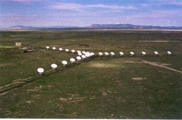
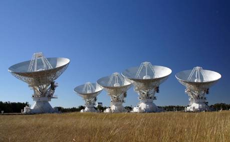
JVLA: The Jansky Very Large Array is
situated in New Mexico at an altitude of 2124m. In this picture the 27 25-m
antennas are in the most compact “D-array” configuration. The antennas can be
relocated onto a series of different station pads to make distinct arrays of
maximum baseline 1.03km (D-array); 3.04 km (C-array) 11.4 km (B-array) and 36.4 km (A-array);
intermediate configurations are also possible.An
extensive system upgrade, completed in 2012, provides coverage of the radio spectrumfrom 1 GHz to 50 GHz in 8 different bands with
additional low frequencybands at ∼70 and ∼350 MHz.https://science.nrao.edu/facilities/vla
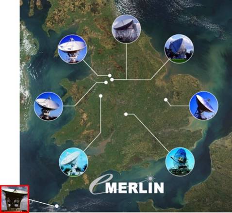
eMERLIN: the
Multi-Element Radio-Linked Interferometer Network, has six fixed telescopes (5 × 25-m; 1 x 32-m) distributed across central England with a maximum
baseline of over 200 km. The array is
now connected by optical fibres to the central site at Jodrell Bank, Cheshire.
For a significant fraction of the observations the 76-m Lovell Telescope
(equivalent in area to nine 25-mdishes) is included in the array. A 25-m
telescope at Goonhilly (at the south western corner
of the map )will be added to the network in 2020, doubling the maximum baseline
and improving u,v coverage for low declination
sources.www.e-merlin.ac.uk
ATCA: The
Australia Telescope Compact Array ) near Narrabri, NewSouth
Walesconsists of six 22-m dishes (of which five are
movable), distributed along an 6km East-West baseline.www.narrabri.atnf.csiro.au

ASKAP: The
Australia Telescope SKA Pathfinder has 36 × 12-m
dishes in fixed locations with baselines covering the range 20m to 6km. It is
primarily aimed at observations around 1 GHz (both continuum and redshifted
atomic hydrogen) and, along with the WSRT, is pioneering the use of phased
array feeds (PAFs; see also Supp Mat Chapter 8) greatly to enhance the survey
speed of the array www.atnf.csiro.au/projects/askap/index.html. The
entire 12-m reflector surface rotates as a sky field is tracked in order to
maintain a fixed angle between the PAF elements and the sky; this greatly
facilitates calibration.

MeerKAT: is
situated in the Karoo desert of South Africaand was
officially opened in July 2018. It consists of 64×13.5-m offset
Gregorian dishes in fixed
locations with baselines up to 8km. It
is currently the largest and most sensitive radio telescope in the southern
hemisphere until the SKA1-mid is
completed on the same site in the mid-2020s. www.ska.ac.za/science-engineering/meerkat
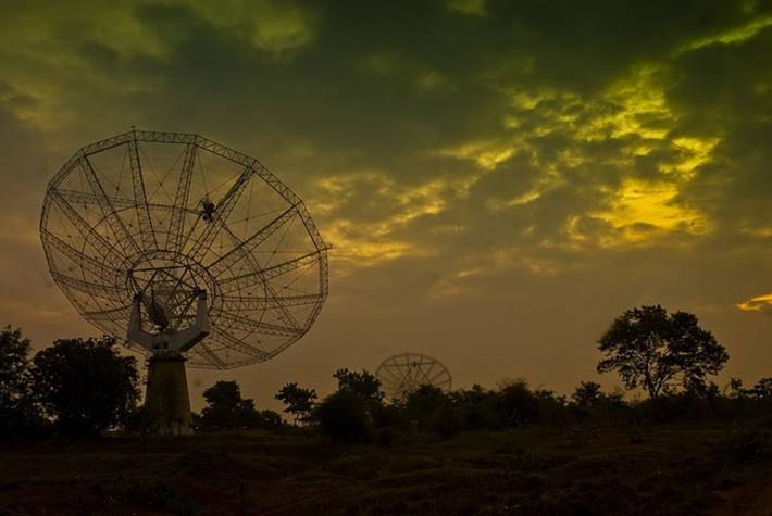
GMRT: the Giant
Metre-wave Radio Telescope near Pune, India is designed to operate at frequencies from 50
MHz to 1.4 GHz. The array consists of 30 × 45-m
dishes in fixed locations; there is a central 1 km ”core”
containing 12 dishes with the other 18 dishes in a Y-shaped configuration
providing baselines up to 25 km. A major upgrade in sensitivity and frequency
coverage was completed
in 2018 www.gmrt.ncra.tifr.res.in .
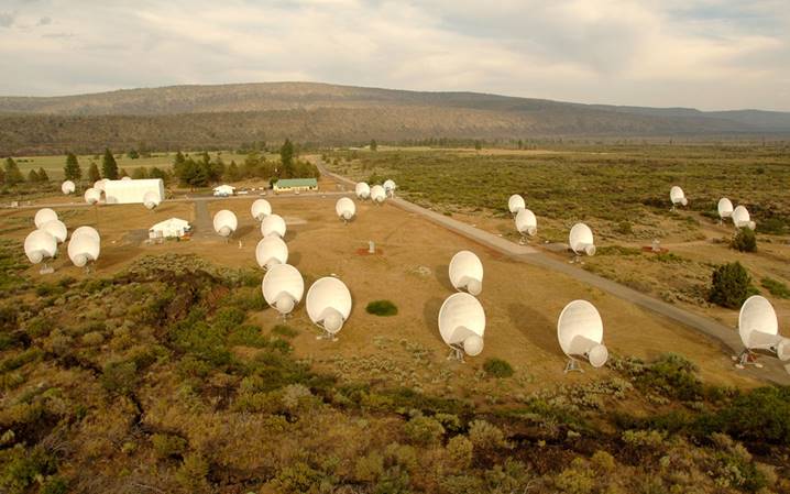
ATA: the Allen
Telescope Array in Hat Creek, California was designed principally for the
Search for Extraterrestrial Intelligence (SETI). It
has 42×6-m offset parabolic dishes with
baselines to 300m. The design includes many technical innovations to allow the
array to carry out wide area surveys over a wide range of frequencies (∼1 to ∼10 GHz)(credit:Seth Shostak/SETI
Institute).https://www.seti.org/articles/allen-telescope-array
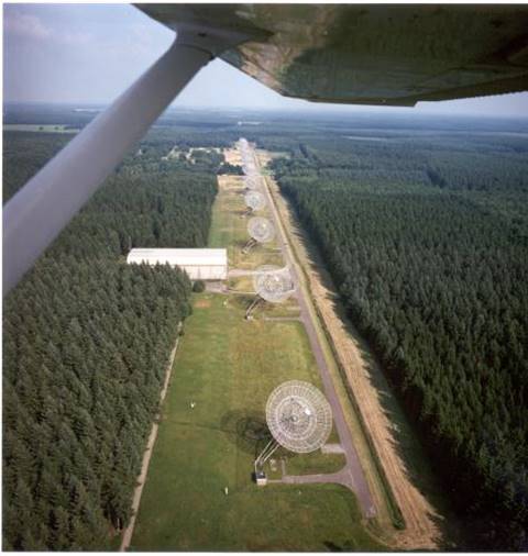
WSRT: the Westerbork Synthesis Radio Telescope has ten fixed and four
movable 25-m dishes. The array is
currently (2018) being transformed into an efficient 21cm L-band survey
facility by replacing the front-ends in 12 telescopes with APERTIF phased array
feeds (see also Supp Mat Chapter 8). https://www.astron.nl/radio-observatory/astronomers/wsrt-astronomers
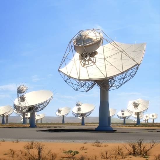
SKA-mid Africa:(artist’s impression) the first phase
of the Square Kilometre Array dish array will be built on the same site and
linked together with the SKA-SA MeerKat Array to form
SKA1-mid Africa The 15m SKA dishes have
an offset feed arrangement and the receiver bands extend over the frequency
range ~350 MHz to ~14 GHz. The combined
array will have ~200 dishes and with a maximum baseline of 150 km; it will be the most powerful
centimetric radio array in the world.https://www.skatelescope.org/africa/